Door Security Controller
ESP32-S3 door controller — 12V latch driver and reed-switch input on a 2-layer carrier for the ESP32-S3-DevKitC.
A simple but seriously-built door access controller for a workshop or studio. Designed to keep working when the network drops, the mains drops, or someone tries to pull the unit off the wall.
The TPS27S100 smart switch drives a fail-secure 12V latch with current sensing (so a short or a stuck latch is logged, not just smoke). The BQ25895 charger provides hot-swappable 18650 backup so a brief mains glitch doesn't lock anyone out (or in).
Inspired by Blueprint.am's "home security control board" example.
| MCU Module | ES-01 ESP32-S3-DevKitC-1 | Plugs into 2x 1x22 pin headers (J1/J2) |
| Latch Driver | DR-01 AO3400A N-MOSFET | Low-side switch, SOT-23, 30V/5.8A |
| Latch Protection | PR-01 1N4007 flyback | SMA, across the latch coil |
| Reed Input | SE-01 Screw terminal → GPIO6 | ESP32 internal pull-up enabled in firmware |
| Power Inputs | PW-01 USB-C (logic) + 12V terminal (latch) | Two isolated rails — logic stays alive if latch supply drops |
| Board | PB-01 2-layer, 80 × 100 mm | 13 components, auto-routed end-to-end (0S/0U) |
| Ref | Category | MPN | Description | Qty | Unit | Ext | Stock | Links |
|---|---|---|---|---|---|---|---|---|
| J1 | PinHeader_1x22 | PinHeader_1x22_2.54mm | 1x22 0.1in pin header | 1 | $0.30 | $0.30 | — | LCSC |
| J2 | PinHeader_1x22 | PinHeader_1x22_2.54mm | 1x22 0.1in pin header | 1 | $0.30 | $0.30 | — | LCSC |
| J3 | Phoenix_MPT_2P | MPT 0.5/2-2.54 | 2-pin 2.54mm screw terminal | 1 | $0.45 | $0.45 | — | DS LCSC |
| J4 | Phoenix_MPT_2P | MPT 0.5/2-2.54 | 2-pin 2.54mm screw terminal | 1 | $0.45 | $0.45 | — | DS LCSC |
| J5 | Phoenix_MPT_2P | MPT 0.5/2-2.54 | 2-pin 2.54mm screw terminal | 1 | $0.45 | $0.45 | — | DS LCSC |
| Q1 | SOT-23 | AO3400A B | N-channel MOSFET 30V 5.8A | 1 | $0.05 | $0.05 | In stock | DS LCSC |
| D1 | SMA | 1N4007 | 1A 1000V flyback diode | 1 | $0.0062 | $0.0062 | In stock | DS LCSC |
| D2 | LED_0805 | LTST-C170KGKT | Green 0805 LED | 1 | $0.02 | $0.02 | In stock | DS LCSC |
| R1 | R_0402 | RC0402FR-0710KL | 10k 0402 1% | 1 | $0.0004 | $0.0004 | In stock | DS LCSC |
| R2 | R_0402 | RC0402FR-0710KL | 10k 0402 1% | 1 | $0.0004 | $0.0004 | In stock | DS LCSC |
| R3 | R_0402 | RC0402FR-071KL | 1k 0402 1% | 1 | $0.0004 | $0.0004 | In stock | DS LCSC |
| C1 | C_0402 | CL05B104KO5NNNC B | 100nF 50V X7R 0402 | 1 | $0.0008 | $0.0008 | In stock | DS LCSC |
| C2 | C_0805 | CL21A106KAYNNNE B | 10uF 25V X5R 0805 | 1 | $0.0068 | $0.0068 | In stock | DS LCSC |
| Total | $2.03 | |||||||
Real KiCad schematic auto-generated from the designgraph TOML by gen_kicad_schematic.py. Each component is a generic block symbol with N pins; nets connect via local + global labels (label-based connectivity, no wires drawn). The .kicad_sch file opens in eeschema and exports to SVG via kicad-cli.
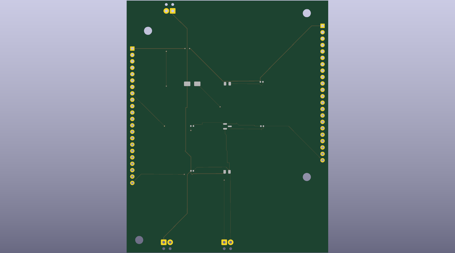
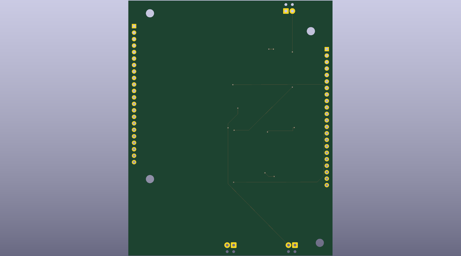
2-layer board, 80 × 100 mm, auto-routed by the Rust VG router. 32 traces, 8 vias, 0 shorts, 0 unconnected. F.SilkS engineering cartouche added in the BR corner.


- Phase 01 Order PCBTools: JLCPCB account
- Run `target/release/pipeline hardware/design/door-sec/main.toml hardware/design/door-sec/door-sec.kicad_pcb` to regenerate the PCB.
- Open in KiCad to manually clean the 9 silk/edge-clearance violations (or wait for the convergence loop to fix them automatically).
- Export gerbers via `kicad-cli pcb export gerbers`.
- Upload to JLCPCB. 2-layer, 1.6mm, HASL or ENIG, qty 5 → ~$10 incl. shipping.
- Phase 02 Order partsTools: LCSC cart
- Open `site/src/projects/door-sec-bom.csv` and copy the LCSC column into the LCSC bulk import tool.
- Total parts cost ~$2.20/board (passives + AO3400A + screw terminals).
- ESP32-S3-DevKitC-1 ordered separately from the manufacturer or AliExpress (~$8).
- Phase 03 AssembleTools: Soldering iron, Solder, Flux, Tweezers
- Hand-solder the SOT-23 MOSFET (Q1), SMA diode (D1), and 0805 LED first.
- Hand-solder all 0402 passives (R1, R2, R3, C1).
- Reflow or hand-solder the 0805 cap (C2).
- Solder pin headers (J1, J2) for the ESP32-S3-DevKitC socket.
- Solder screw terminals (J3, J4, J5) last.
- Plug in the ESP32-S3-DevKitC-1 module.
- Phase 04 Bring-upTools: Multimeter, 12V bench supply (current-limited 100 mA)
- With no module installed, ohm out V12 ↔ GND on J3. Should be many MΩ.
- Apply 12V via current-limited supply. Should draw <5 mA quiescent (just the diode and cap leakage).
- Plug in the DevKitC and confirm 3.3V appears at J1.1.
- Flash a Blink sketch toggling GPIO5 — D2 should light, and Q1's drain should toggle low (measure at J4.2).
- Short J5.1 to J5.2 to simulate a closed reed switch — GPIO6 should read low (with internal pull-up enabled).